
Page 57 - JSOM Spring 2020
P. 57
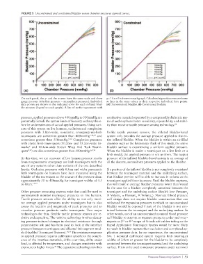
FIGURE 5  Unconstrained and constrained bladder versus chamber pressures sigmoid curves.


               (A)                                                (B)

              On each panel, the y- and the x-axes have the same scale and show   y = 1 ✕ x + 0 is shown on each graph. Calculated sigmoid curves are shown
              gauge pressure (absolute pressure – atmospheric pressure). Individual   as lines in the same colors as their respective individual data points.
              data points are shown in the indicated color for each inflated blad-  (A) Unconstrained bladder. (B) Constrained bladder.
              der pressure (legend on each graph). A line of perfect agreement with


              pressure, applied pressures above 400mmHg to 550mmHg are   conductive material separated by a compressible dielectric ma-
              potentially outside the system limits of linearity and may there-  terial and may have better sensitivity, repeatability, and stabil-
              fore be underestimates of actual applied pressures. Using vari-  ity than resistive tactile pressure sensing technology. 21
              ants of this system on live humans, occlusion and completion
              pressures with 3.8cm-wide, nonelastic, emergency-use-limb   Unlike tactile pressure sensors, the inflated bladder-based
              tourniquets are sometimes greater than 400mmHg 9-12,14  and   system only provides the average pressure applied to the en-
              sometimes greater than 550mmHg. 9-12  Completion pressures   tire inflated bladder. When the bladder is within an air-filled
              with elastic limb tourniquets (10.2cm- and 15.2cm-wide Es-  chamber such as the Erlenmeyer flask of this study, the entire
                  6
              marks  and 10.4cm-wide  Stretch Wrap And Tuck Tourni-  bladder surface is experiencing a uniform applied pressure.
              quets 9,12 ) are also sometimes greater than 400mmHg. 6,9,12  When the bladder is under a tourniquet on a live limb or a
                                                                 limb model, the applied pressure is not uniform. The output
              At this time, we are unaware of live human pressure results   pressure of the inflated bladder-based system is an average of
              from nonpneumatic emergency use limb tourniquets with the   all the discrete, nonuniform pressures applied to the bladder.
              use of any systems other than variants of the one described
              herein. Occlusion pressures with 4.5cm and wider pneumatic   If a portion of the inflated bladder is not completely contained
              limb tourniquets on humans have been measured using the   between the tourniquet material and the underlying surface,
              bladder of the tourniquet as the source of the pressure data:   that bladder portion will be able to increase in volume as the
              approximately 50 to 430mmHg for tourniquet widths of 4.5   tourniquet-applied force increases. Until the bladder ruptures,
              to 80cm. 15-17                                     this will result in average bladder pressures lower than would
                                                                 be the case for a bladder completely contained between the
              Other pressure measuring systems exist that could be used to   tourniquet and the underlying surface (Boyle’s law: Pressure
                                                                                                                1
              noninvasively monitor tourniquet pressures on live humans.   ✕ Volume  = Pressure  ✕ Volume ). Neonatal blood pressure
                                                                                           2
                                                                                  2
                                                                         1
              Tactile pressure sensors offer the ability to not only moni-  cuff design does not require bladder  construction that can
              tor average applied pressures under tourniquets but to also   withstand the expansion pressures to which an unconstrained
              assess the location and magnitude of peak pressures and to   bladder would be exposed if part of the bladder is not con-
              visualize pressure gradients under tourniquets. Two major   tained between the tourniquet and the underlying surface. In
              technologies for thin, flexible tactile pressure sensors are re-  other words, use of an unconstrained neonatal blood pressure
              sistive and capacitive. The resistive technology involves detect-  cuff bladder to attempt to measure pressures under such tour-
              ing pressure-induced changes in electrical resistance through   niquets as 2  or 4  wraps of ½-inch soft rubber tubing or the
                                                                               23
                                                                          22
              piezoresistive ink and has been used to look at the interface   Rapid Application Tourniquet System would be more likely
              pressure between tourniquets and silicone limb-segment mod-  to result in bladder rupture than occlusion and completed ap-
              els (HapMed Tourniquet Trainers). 18,19  The resistance response   plication pressure data. In our experience, the unconstrained
              to applied pressure requires calibration specific to the compli-  No. 1 neonatal cuff-based system requires limb tourniquet
              ance of the interface materials, drifts over time, drifts under   widths of 3.8cm or greater for the bladder to be completely
              load, is affected by temperature, and changes sensitivity with   contained between the tourniquet material and the underlying
                                 20
              exposure to higher forces.  The capacitive technology involves   surface. If it is to be used to measure pressures under narrower
                                                                                         Pressure Measuring System  |  53