
Page 40 - JSOM Winter 2017
P. 40
Intertourniquet distances with the paired RMTs were con- monitoring locations were the dorsal pedal artery on the top
trolled by joining the tourniquets to each other with four cir- of the foot or the posterior tibial artery at the ankle. The
cumferentially distributed, fixed length tethers (Figure 1A). audible pulse signal had to remain absent with the ratchet-
Tourniquet placement locations on each thigh were traced onto ing buckle returned to its rest position and all hands off the
the skin using a template and a marker. The placement loca- tourniquet for occlusion pressure. With the single tourniquets,
tions were distal (a fixed location) and 0, 2, 4, 8, and 12cm tightening to occlusion occurred tooth-by-tooth as the pawl
intertourniquet distances moving proximally (Figure 1A). A advanced along the single tourniquet ladder. With the paired
randomized block design via paper draw was used to assign tourniquets, the ratcheting buckle of the distal tourniquet was
the order of placement locations for each recipient. For each advanced one tooth first; then the ratcheting buckle of the
location, the order of tourniquet use was pair, distal, proximal. proximal tourniquet was advanced one tooth. This alternation
continued to one-tooth advance past occlusion to complete the
Pressure Measurements application.
Pressures under each tourniquet were measured using a No. 1
neonatal blood pressure cuff (2.2cm × 6.5cm bladder, single Completion Pressure
tube). Each cuff bladder was inflated to 10-12mmHg above Completion was defined as one-tooth advance past occlusion
atmospheric pressure to avoid complete collapse of the blad- with all hands off the tourniquet.
der during tourniquet applications. Atmospheric pressure was
used as baseline pressure. Each cuff was taped to each tourni- 120-Second Pressure
quet under the strap just beyond the ratcheting buckle attach- Following completion, the tourniquet was secured for 125sec-
ment rivet. onds. We defined the 120-second pressure as the pressure
120seconds after completion pressure. If the audible pulse
Each inflated bladder was connected to a gas pressure sensor signal returned within 120seconds of completion, that return
system (Vernier Gas Pressure Sensor, Vernier LabPro interface, time and pressure were noted, indicating failure of the tour-
and Logger Pro Software; Vernier Software and Technol- niquet to maintain arterial occlusion. Following each tour-
ogy, www.vernier.com). Pressure was continuously displayed niquet’s release after the 120-second pressure was recorded,
graphically with numeric values displayed every second. Each the return (or absence) of the audible pulse signal was noted.
tourniquet application’s data was saved as complete, com- Return of the audible pulse signal confirmed that prior au-
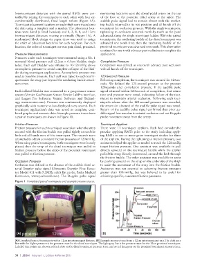
bined graphic and numeric data. Example pressure traces from dible signal loss was due to arterial occlusion and not Doppler
a pair of tourniquets are shown in Figure 1B. probe movement away from the artery.
Friction Pressure Tourniquet Appliers
Friction pressure for each tourniquet was taken when the strap There were 11 tourniquet appliers. Each had considerable
secured with the friction buckle was pulled tightly around the practice applying RMTs prior to the study including apply-
limb and all hands were off the tourniquet. The research team ing RMTs in one or more prior tourniquet studies for three
attempted to obtain consistent friction pressures of 120mmHg. of the appliers. During the tightening to friction pressure, two
When using paired tourniquets, both tourniquets were loosely assistants helped the applier as needed to reach the 120mmHg
placed; then the strap of the distal tourniquet was pulled to target friction pressure. One assistant was available to pull
friction pressure before the strap of the proximal tourniquet directly upward on the tourniquet handle while the applier
was pulled to friction pressure. pulled the strap directly downward, around the limb through
the friction buckle. The other assistant was available to assist
Occlusion Pressure by pushing upward on the strap on the underside of the thigh
Occlusion was defined as the absence of the audible distal ar- to assist the movement of the strap into the friction buckle.
terial Doppler pulse signal (Ultrasonic Doppler Flow Detec- Assistance was not essential to achieving friction pressures
tor Model 811 with 9.5MHz adult flat probe; Parks Medical greater than 100mmHg, but was believed to be useful for
Electronics, www.parksmed.com). The Doppler pulse signal achieving specific, consistent friction pressures.
Figure 1 Completed paired tourniquets and example pressure traces.
(A) (B)
(A) Completed paired tourniquets with a 12cm intertourniquet distance. (B) Example pressure trace from a 12cm intertourniquet pair. The dark gray
line with the higher pressure is the pressure trace for the distal tourniquet. The light gray line is the pressure trace for the 12cm proximal tourniquet.
Labeled time points are shown as black dots on the distal tourniquet pressure trace and as red hexagons on the proximal tourniquet pressure trace.
38 | JSOM Volume 17, Edition 4/Winter 2017