
Page 42 - Journal of Special Operations Medicine - Winter 2014
P. 42
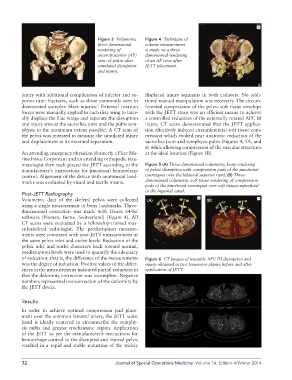
Figure 3  Volumetric   Figure 4  Technique of
                                         three-dimensional   volume measurement
                                         rendering of        is made on a three-
                                         anteroposterior (AP)   dimensional rendering
                                         view of pelvis after   of an AP view after
                                         simulated disruption   JETT placement.
                                         and injury.


          injury with additional complication of inferior and su-  displaced injury segments in both cadavers. No addi-
          perior rami fractures, such as those commonly seen in   tional manual manipulation was necessary. The circum-
          dismounted complex blast injuries.  External rotation   ferential compression of the pelvic soft tissue envelope
                                         6
          forces were manually applied to each iliac wing to later-  with the JETT strap was an efficient means to achieve
          ally displace the iliac wings and separate the disruption   a controlled reduction of the externally rotated APC III
          and injury sites at the sacroiliac joint and the pubis sym-  injury. CT scans demonstrated that the JETT applica-
          physis to the maximum extent possible. A CT scan of   tion effectively induced circumferential soft tissue com-
          the pelvis was repeated to measure the simulated injury   pression which evoked near anatomic reduction of the
          and displacement at its maximal separation.        sacroiliac joint and symphysis pubis (Figures 4, 5A, and
                                                             6) while allowing compression of the vascular structures
          An attending emergency physician (formerly a Fleet Ma-  at the ideal location (Figure 5B).
          rine Force Corpsman) and an attending orthopedic trau-
          matologist then each placed the JETT according to the   Figure 5 (A) Three-dimensional volumetric bony rendering
          manufacturer’s instructions for junctional hemorrhage   of pelvic disruption with compression pads of the junctional
          control. Alignment of the device with anatomical land-  tourniquet over the bilateral superior rami. (B) Three-
          marks was evaluated by visual and tactile means.   dimensional volumetric soft tissue rendering of compression
                                                             pads of the junctional tourniquet over soft tissues superficial
                                                             to the inguinal canal.
          Post-JETT Radiography
          Volumetric  data  of  the  skeletal  pelvis  were  collected   (A)          (B)
          using a single measurement of bony landmarks. Three-
          dimensional correction was made with Osirix 64-bit
          software (Pixmeo, Berne, Switzerland) (Figure 4). All
          CT scans were evaluated by a fellowship-trained mus-
          culoskeletal radiologist. The predisruption measure-
          ments were compared with post-JETT measurements at
          the same pelvis inlet and outlet levels. Reduction of the
          pelvic inlet and outlet diameters back toward normal,
          predisruption levels were used to quantify the adequacy
          of reduction; that is, the difference of the measurements   Figure 6  CT images of unstable APC III disruption and
          was the degree of reduction. Positive values of the differ-  injury obtained in two transverse planes before and after
          ences in the measurements indicated partial reduction in   application of JETT.
          that the deformity correction was incomplete. Negative
          numbers represented overcorrection of the deformity by
          the JETT device.


          Results
          In order to achieve optimal compression pad place-
          ment over the common femoral artery, the JETT waist
          band is ideally centered to circumscribe the symphy-
          sis pubis and greater trochanteric region. Application
          of the JETT as per the manufacturer’s instructions for
          hemorrhage control to the disrupted and injured pelvis
          resulted in a rapid and stable reduction of the widely


          32                                     Journal of Special Operations Medicine  Volume 14, Edition 4/Winter 2014