
Page 53 - JSOM Fall 2022
P. 53
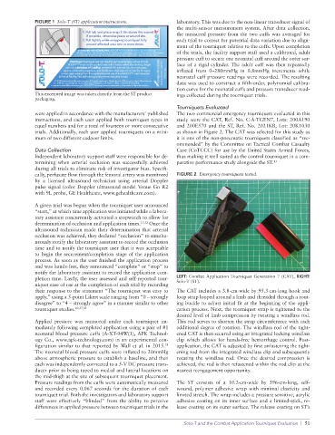
FIGURE 1 Solo-T (ST) application instructions. laboratory. This was due to the nonlinear transducer signal of
the multisensor measurement system. After data collection,
the measured pressure from the two cuffs was averaged for
each trial to correct for potential data variation due to align
ment of the tourniquet relative to the cuffs. Upon completion
of the trials, the facility support staff used a calibrated, adult
pressure cuff to secure one neonatal cuff around the outer sur
face of a rigid cylinder. The adult cuff was then repeatedly
inflated from 0–280mmHg in 0.8mmHg increments while
neonatal cuff pressure readings were recorded. The resulting
data was used to construct a fifthorder, polynomial calibra
tion curve for the neonatal cuffs and pressure transducer read
This excerpted image was taken directly from the ST product ings collected during the tourniquet trials.
packaging.
Tourniquets Evaluated
were applied in accordance with the manufacturers’ published The two commercial emergency tourniquets evaluated in this
instructions, and each user applied both tourniquet types in study were the CAT, Ref. No. C·A·TGEN7, Lots: 200A190
equal numbers and for a total of fourteen or more consecutive and 200E570 and the ST, Ref. No. 2021KB, Lot: 20K1030
trials. Additionally, each user applied tourniquets on a mini as shown in Figure 2. The CAT was selected for this study as
mum of two different cadaver limbs. it is one of the nonpneumatic tourniquets classified as “rec
ommended” by the Committee on Tactical Combat Casualty
Data Collection Care (CoTCCC) for use by the United States Armed Forces,
Independent laboratory support staff were responsible for de thus making it well suited as the control tourniquet in a com
termining when arterial occlusion was successfully achieved parative performance study alongside the ST. 13
during all trials to eliminate risk of investigator bias. Specifi
cally, perfusate flow through the femoral artery was monitored FIGURE 2 Emergency tourniquets tested.
by a licensed ultrasound technician using arterial Doppler
pulse signal (color Doppler ultrasound model Venue Go R2
with 9L probe, GE Healthcare, www.gehealthcare.com).
A given trial was begun when the tourniquet user announced
“start,” at which time application was initiated while a labora
tory assistant concurrently activated a stopwatch to allow for
determination of occlusion and application times. 17,32 Once the
ultrasound technician made their determination that arterial
occlusion was achieved, they declared “occlusion” to simulta
neously notify the laboratory assistant to record the occlusion
time and to notify the tourniquet user that it was acceptable
to begin the securement/completion stage of the application
process. As soon as the user finished the application process
and was handsfree, they announced “complete” or “stop” to
notify the laboratory assistant to record the application com
pletion time. Lastly, the user assessed and selfreported tour LEFT: Combat Application Tourniquet Generation 7 (CAT), RIGHT:
SoloT (ST).
niquet ease of use at the completion of each trial by recording
their response to the statement “The tourniquet was easy to The CAT includes a 3.8cmwide by 95.3cmlong hook and
apply,” using a 5point Likert scale ranging from “0 – strongly loop strap looped around a limb and threaded through a rout
disagree” to “4 – strongly agree” in a manner similar to other ing buckle to adjust initial fit at the beginning of the appli
tourniquet studies. 20,27,30 cation process. Next, the tourniquet strap is tightened to the
desired level of limb compression by twisting a windlass rod.
Applied pressure was measured under each tourniquet im This rod serves to shorten the strap circumference with each
mediately following completed application using a pair of #1 additional degree of rotation. The windlass rod of the tight
neonatal blood pressure cuffs (AXT04W(1), APK Technol ened CAT is then secured using an integrated locking windlass
ogy Co., www.apktechnology.com) in an experimental con clip which allows for handsfree hemorrhage control. Post
figuration similar to that reported by Wall et al. in 2015. application, the CAT is adjusted by first unfastening the tight
31
The neonatal blood pressure cuffs were inflated to 20mmHg ening rod from the integrated windlass clip and subsequently
above atmospheric pressure to establish a baseline, and then rotating the windlass rod. Once the desired compression is
each was independently connected to a 5V DC pressure trans achieved, the rod is then refastened within the rod clip at the
ducer prior to being taped to medial and lateral locations on nearest reengagement opportunity.
the midthigh at the site of subsequent tourniquet placement.
Pressure readings from the cuffs were automatically measured The ST consists of a 10.2cmwide by 396cmlong, self
and recorded every 0.067 seconds for the duration of each wound, polymer adhesive wrap with minimal elasticity and
tourniquet trial. Both the investigators and laboratory support limited stretch. The wrap includes a pressure sensitive, acrylic
staff were effectively “blinded” from the ability to perceive adhesive coating on its inner surface and a limitedstick, re
differences in applied pressure between tourniquet trials in the lease coating on its outer surface. The release coating on ST’s
Solo-T and the Combat Application Tourniquet Evaluation | 51