
Page 96 - JSOM Fall 2023
P. 96
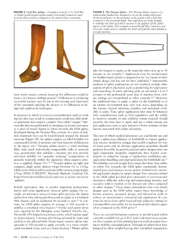
FIGURE 2. Civil War splints – Examples from the U.S. Civil War   FIGURE 3. The Thomas Splint – The Thomas Splint consists of a
          of simple prefabricated splints made from hand-formed wooded   semicircular padded bar designed to sit on the ischial tuberosity
          sections that would be strapped to the injured lower extremity.  (bony prominence on the posterior of the pelvis) with a belt that
                                                             secures it to the proximal thigh. Two rigid bars protrude distally
                                                             to stabilize the limb and allow traction to be applied off the distal
                                                             aspect of the splint. This example is from World War I and does not
                                                             show the straps used to stabilize the limb and pull the limb distally to
                                                             provide traction.


                                                             take the longest to apply, as the materials often take up to 30
                                                             minutes to set properly.  Application time for prefabricated
                                                                                37
                                                             air bladder-based splints is suspected to be low based on their
                                                             simple design but has not yet been published.  Importantly,
                                                                                                  36
                                                             analyses of splint applications do not routinely include other
                                                             aspects of splint placement, such as positioning for application
                                                             and unpacking. In total, splinting adds an estimated 1.8 to 9
          have active muscle control, meaning the differences could be   minutes to the prehospital scene time if statistics from civil-
          from a live human shifting around.  Differences in producing   ian settings are extrapolated to other contexts. 38,39  However,
                                     23
          successful traction may be due to the training and experience   the additional time to apply a splint on the battlefield or in
          of the personnel applying the devices or to differences in de-  an austere environment may vary even more, depending on
          sign and application techniques.                   the terrain, tactical situation, weather, and personnel avail-
                                                             able to assist. Thus, splint application time must be balanced
          In instances in which traction is contraindicated, such as crush   with considerations such as field expediency and the ability
          injuries that may result in compartment syndrome, field medi-  to improve casualty or unit mobility. Future research should
          cal personnel may employ a simple “box splint” design.  His-  quantify the total time to apply and use a splint system, not
                                                     27
          torically, this was performed by strapping an injured extremity   just application time, to give rescuers a better estimate of time
          to a piece of wood (Figure 2). More recently, the SAM splint,   factors associated with splint utilization.
          developed during the Vietnam War, consists of a sheet of pad-
          ded aluminum that can be hand-formed around the injured   The ease of which medical personnel can confidently use and
          anatomy (Figure 1B). Air splints employ air-filled bladders for   apply a splint may influence its battlefield or remote applica-
          customizable levels of pressure and thus fracture stabilization   tion success. Intuitively, designs that model simplicity by way
          at the injury site. Vacuum splints involve a vinyl envelope   of fewer parts and an obvious application procedure should
                        33
          filled with small individually-compressible balls of material   perform favorably. In general, traction splint designs with one
          (e.g., polystyrene) that stabilize a fracture and may provide   rigid component (unipolar) outperform their bipolar coun-
          structural stability via “granular jamming” (compression  of   terparts  in subjective  ratings of  application  confidence, pre-
          granular materials within the apparatus when negative pres-  application handling, and appropriateness for battlefield use.
                                                                                                            23
          sure is applied) (Figure 1C). 34–36  Vacuum splints are light and   Nevertheless, several designs have issues that limit their utility
          compact; single splint options weigh between 0.2 to 1.0-kg,   or safety. For example, the SAM splint consistently demon-
          while a case of three splints and a portable vacuum pump weighs     strated poor performance across metrics related to its success-
          2.9-kg  (EVAC-U-SPLINT ,  Hartwell  Medical,  Carlsbad  CA,   ful application despite its simple design. User concerns related
                              ®
          https://www.hartwellmedical.com/evac-u-splint-extremity   to the SAM splint included poor protection of neurovascular
          -splints/).                                        structures, difficulty achieving and maintaining traction, and
                                                             excessive relative motion at the fracture site when compared
          In-field application time is another important performance   to other designs.  These issues demonstrate that even simple
                                                                          26
          metric and varies significantly between splint designs. For ex-  designs such as the SAM splint require basic knowledge of
          ample, an innovative spray-on foam splint provides the fastest   human anatomy, structural design, and fabrication skills to
          application time, taking just 68 seconds to apply to a simulated   achieve an appropriately contoured safe application. In con-
                                                   26
          tibia fracture and an additional 60 seconds to cure.  In con-  trast, the spray-foam splint received high subjective ratings on
          trast, the SAM splint requires an average of 203 seconds to   reproducibility and ability for an untrained individual to apply
          stabilize a simulated tibia fracture.  Similar application times   when compared to the SAM splint. 26
                                     26
          were reported for the fiberglass wrap, FastSet3 (FareTec Inc.,
          Painesville OH, https://www.faretec.com/), which reaches rigid-  There are several limitations common to prefabricated splints
          ity approximately 3 minutes after being activated by water and   currently available for use in PCC and wilderness rescue scenar-
          applied to the affected limb. Frame-based traction splints take   ios. For example, in-field splinting has not enabled weight-bear-
          upwards of 350 seconds to apply correctly to a more compli-  ing or mobility post-application. Although air splints have been
                                              23
          cated simulated injury, such as a femur fracture.  Plaster splints   designed to allow weight bearing after transtibial amputation,
          94  |  JSOM   Volume 23, Edition 3 / Fall 2023