
Page 45 - JSOM Summer 2019
P. 45
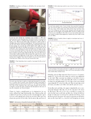
FIGURE 2  Detailing a technique to self-adhere the tourniquet band   FIGURE 4  Chart depicting results in ease of use by time to apply a
              between the clips.                                 tourniquet.


                                                                 For each user, greater ease of use (circles) was associated negatively
                                                                 with time taken to apply the tourniquet (dots show linear regressions).
                                                                 The data range of the expert user (blue circles) was narrower than
                                                                 that of the competent user (red circles). Because each user performed
                                                                 with their own tourniquet, the materiel effect (framed as either model
                                                                 or device) was controlled so that effect on ease was attributable to the
                                                                 user, namely accrual of their experience. In this way, ease could be seen
                                                                 as a user effect.
              A close-up view details the tourniquet seen in Figure 1. The self-
              adhering band is seen dangling down behind the white time strap at the   FIGURE 5 Chart of results of time to apply a tourniquet and ease of
              left. The time strap is a tourniquet part which is used to secure the rod   use by use number.
              within a clip. The smooth, fabric side of the band is visible, while its
              self-adhering surface is hidden on the flipside. The band passes between
              the two clips, which have their C-shapes open and facing each other.
              In this passage, the smooth side of the band is still easily seen, and
              underneath that side the self-adhering surfaces are sandwiched facing
              each other. That facing occurs after the band routes through the bot-
              tom slit in the buckle where it folds over the bottom bar of the buckle
              to return toward the clips. Thus, the band has its self-adhering surface
              facing itself through the region between the clips. The user, after having
              removed the band’s slack, had then pressed the band onto the under-
              lying tourniquet and limb here in this region so that the self-adhering
              surfaces stuck together. Note that the band is not over the clips and not
              blocking access of the rod into the gap between the clips.

              FIGURE 3  Chart depicting time to apply a tourniquet by the accrual
              of its uses.


                                                                 For the average of two users, the time to apply the tourniquet (purple
                                                                 circles) decreased asymptotically. Their ease of use (open green circles)
                                                                 was a similar but inverted trend.

                                                                 both the rod and clips separated them by an arc of approxi-
                                                                 mately 90°. As the rod was turned, its rotation was tangential
                                                                 to the limb. This is normal in relation to the limb, but it is
                                                                 abnormal in relation to the clips when the limb is so small. In
              For each user, the time to apply a tourniquet decreased by use num-  turning, the rod ends passed over the clips, which were angled
              ber in a power law of practice. The expert user (blue circles) had an   approximately 90° away from the rod: The rod and clips could
              estimated initial time that was 42% ([116.75 − 67.994]/116.75) faster   not meet, so neither end of the rod could be put into a clip.
              than that of the competent user (red circles). Results of both users
              eventually overlaid the same asymptote: By this metric in this type of
              use, the competent user became expert.             Given this new problem, the expert immediately saw an un-
                                                                 expected solution—that the role of the clip was to be taken
              (Figure 6). Again, a modification to the instructions for use   by the band. The role of the clip is normally to secure the
              was to adhere the band between the clips. However, the rod   rod, but the band could take up that role. Given the leftover
              could not be put into a clip because the rod and clip were apart   length in band after encircling the medium-sized limb, excess
              and they were angled away from one another. Their gap was   band remained. Also given the expert’s experience in 100 prior
              about one-quarter of the circle. On the circle, the positions of   uses on the large limb (i.e., handrail) and wrapping its excess

              TABLE 1  Information About the Simulated Limbs of Infants
                                                 Material of                     Shape of Limb      Perimeter
                 Limb Girth   Simulator of Limb  Simulated Limb   Limb Orientation  in Cross Section  Circumference (in.)
                   Large         Handrail          Steel         Horizontal         Circle            5.25
                  Medium           Pipe            Steel          Vertical          Circle            4.25
                   Small           Pole            Steel          Vertical          Circle            3.25


                                                                                 Tourniquets on Simulated Infant Limbs  |  43