
Page 23 - JSOM Summer 2023
P. 23
cuff, and severing or puncturing of components. Investigators human stomach that is likely to come into contact with the
14
(CB, DZ, MG, SS) performed the MIL-STD tests, operational test devices during their clinical deployment. Using hemo-
checks, and visual examinations, allowing for the score of each static pliers, we submerged each test device into the acid, then
device to be determined. Whenever the investigators provided immediately removed it. The device remained above the acid
different scores, the mean score was used. container and was rotated about its axial direction for 3 min-
utes, allowing the device to drain. We then thoroughly rinsed
Shock Test Method each device with water to decontaminate the devices. After
The purpose of the shock test was to determine the device’s cleaning, we performed a visual examination and operational
ability to withstand a mechanical shock. For the test, we check. After the operational check, we placed the devices in-
dropped test devices from a height of 14 feet to simulate a side chemical-resistant trays and applied HCl to the devices
worst-case but survivable impact scenario. We used three dif- using a poly-fiber brush. We kept the devices wet for 8 hours,
11
ferent geospatial configurations when dropping the devices: then left them in the trays for 16 hours to dry. After drying,
11
the device’s axial direction held parallel to gravity with the we thoroughly rinsed each device with water, then performed
cuff pointed downward, the device’s axial direction held paral- another round of visual examinations and operational checks.
lel to gravity with the vent connector pointed downward, and
the device’s radial direction parallel to gravity with the cuff High Temperature
opening pointed downward (Figure 2). These configurations The purpose of the high temperature test was to determine
11
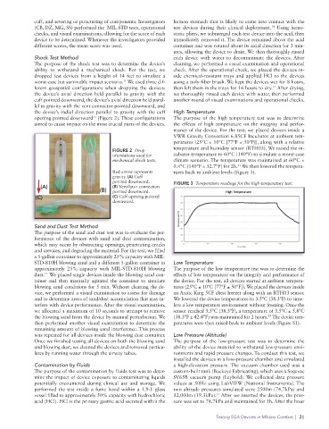
aimed to cause impact on the most crucial parts of the devices. the effects of high temperature on the integrity and perfor-
mance of the device. For the test, we placed devices inside a
VWR Gravity Convection 6.85CF Incubator at ambient tem-
peratures (25°C ± 10°C [77°F ± 50°F]), along with a relative
temperature and humidity sensor (RTH03). We raised the in-
FIGURE 2 Drop
orientations used for cubator temperature to 60°C (140°F) to simulate a worst-case
mechanical shock tests. climate scenario. The temperature was maintained at 60°C ±
11
0.4°C (140°F ± 32.7°F) for 2h. We then lowered the tempera-
Red arrow represents tures back to ambient levels (Figure 3).
gravity. (A) Cuff
pointed downward. FIGURE 3 Temperature readings for the high-temperature test.
(A) (B) Ventilator connection
(B) pointed downward.
(C) (C) Cuff opening pointed
downward.
Sand and Dust Test Method
The purpose of the sand and dust test was to evaluate the per-
formance of the devices with sand and dust contamination,
which may occur by obstructing openings, penetrating cracks
and crevices, and degrading the material. For the test, we filled
a 5-gallon container to approximately 25% capacity with MIL-
STD-810H blowing sand and a different 5-gallon container to Low Temperature
approximately 25% capacity with MIL-STD-810H blowing The purpose of the low temperature test was to determine the
11
dust. We placed single devices inside the blowing sand con- effects of low temperature on the integrity and performance of
tainer and then manually agitated the container to simulate the device. For the test, all devices started at ambient tempera-
blowing sand conditions for 5 min. Without cleaning the de- tures (25°C ± 10°C [77°F ± 50°F]). We placed the devices inside
vice, we performed a visual examination to assess for damage an Arctic King 5CF chest freezer along with an RTH03 sensor.
and to determine areas of sand/dust accumulation that may in- We lowered the device temperatures to 3.5°C (38.3°F) to simu-
terfere with device performance. After the visual examination, late a low temperature environment without freezing. Once the
we allocated a maximum of 10 seconds to attempt to remove sensor reached 3.5°C (38.3°F), a temperature of 3.5°C ± 5.8°C
11
the blowing sand from the device by manual perturbation. We (38.3°F ± 42.4°F) was maintained for 2 hours. The device tem-
then performed another visual examination to determine the peratures were then raised back to ambient levels (Figure S1).
remaining amount of blowing sand interference. This process
was repeated for all devices inside the blowing dust container. Low Pressure (Altitude)
Once we finished testing all devices on both the blowing sand The purpose of the low-pressure test was to determine the
and blowing dust, we cleaned the devices and removed particu- ability of the device material to withstand low-pressure envi-
lates by running water through the airway tubes. ronments and rapid pressure changes. To conduct this test, we
installed the devices in a low-pressure chamber and simulated
Contamination by Fluids a high-elevation pressure. The vacuum chamber used was a
The purpose of the contamination by fluids test was to deter- custom-built tank (Buckeye Fabricating), which uses a Sogevac
mine the impact of device exposure to contaminating liquids SV65B vacuum pump (Leybold). We collected data pressure
potentially encountered during clinical use and storage. We values at 50Hz using LabVIEW (National Instruments). The
performed the test inside a fume hood within a 1.9-L glass two altitude pressures simulated were 2500m (74.7kPa) and
vessel filled to approximately 50% capacity with hydrochloric 12,000m (19.3kPa). After we inserted the devices, the pres-
11
acid (HCl). HCl is the primary gastric acid secreted within the sure was set to 74.7kPa and maintained for 1h. After the hour
Testing SGA Devices in Military Combat | 21